Table of Contents
Updated
In some cases, your system may display a message telling you how to troubleshoot the powerflex 700. There are several possible causes for this problem.
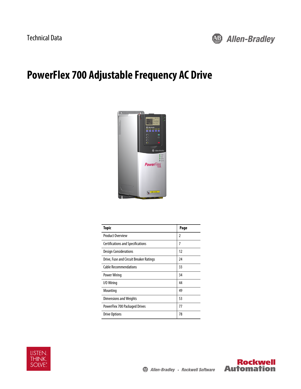
Troubleshooting the Allen Business PowerFlex Bradley 700 AC Drive begins with a fault that occurs during operation or startup. The character of your reader is constantly monitored and any change in location is displayed using the keyboard. An error is a condition in which the inverter must be stopped and corrected before the error can be corrected and the inverter started. Below is a list of errors and possible causes. If the error cannot be cleared, it could mean that the PowerFlex Drive 700 as a whole needs to be repaired.
Error 29 (blank) Loss of analog input – The analog input is optimized for errors in the event of a loss of signal. An indication that a loss has occurred.
Error 108 4. Anlg Cal Chksum – the read checksum, including the analog calibration data, does not contradict the calculated checksum.
Error 33 – Auto RstRun Tries – Execution failed to clear error and continue execution for the programmed number of [Flt RstRun Tries].
Error 80 – Auto-tuning aborted – Auto-tuning function was canceleduser or an error occurred. easy
Fault – auxiliary input – auxiliary advisory lock is open.
Fifty-Five Error – Cntl Bd Overtemp – The temperature sensor on the main control board has detected excessive heat.
Error sixty nine – resistance DB – the resistance of the main internal resistance db is too high.
Error 24 – Deceleration inhibit – The drive does not perform the specified deceleration because it is trying to limit the bus voltage.
Error 64 due to inverter overload, for example, the rated value of the inverter is exceeded 110% for 1 minute or 150% for c seconds.
Updated
Are you tired of your computer running slow? Annoyed by frustrating error messages? ASR Pro is the solution for you! Our recommended tool will quickly diagnose and repair Windows issues while dramatically increasing system performance. So don't wait any longer, download ASR Pro today!

Error 1949 – The drive is on – a very small error is displayed. We use the power-on flag in the error queue to indicate that the drive type was turned off and then back on.
Error seventy nine – Overload – Motor did not reach final speed within the time allowed during autotuning.
Error ninety one – Lost encoder – Differential encoder required. One of two additional code channel signals а is absent.
Fifth error 89 – Encoder Quad Err – Bidirectional encoders changed state in one clock cycle.
Error 900-930 Fatal diagnostic code indicating disk failure.
Error 52 – Error fixed – Error is not displayed. Used like any token in the error queue that indicates the role in which the error recovery function was performed.
Error 51 – – Flt QueueCleared, for example, No error is displayed. Used as an automatic queue error indicating that the type of function to clear the queue was executed.
Error 77 – FluxAmpsRef Rank – The flux amplifier value determined by this autotuning routine exceeds the programmed [Motor NP FLA].
error 13; Ground fault The 3rd ground-to-ground current path is significantly greater than 25% of the rated power of the inverter.
Error ninety – hardware failure – hardware enable disabled (jumper high) but still low on test pin.
Error one hundred and thirty – hardware failure – door range loading error.
Error 131 – hardware failure – dual port is losing money.
Error 18 – Overtemperature between hardware PTC and motor PTC (positive temperature coefficient).
Product error 10) Low temperature heatsink: indicates too low heat generation or an open circuit in the NTC (heatsink temperature sensor).
Error 8 3) OvrTemp heatsink dwarfs 100% [Drive Temp] with heatsink temperature or below -19 ° C.
Error 12, HW OverCurrent 1) The inverter output has exceeded the hardware current limit at the latest.
Error 106: MCB-PB is incompatible because the dimmer power information stored on the effects board is incompatible with the main chord on the board.
Error 121 1) Lost I / O Communication – The I / O board was lost due to sales and marketing messages from the main control board.
Error 122 – I / O error. The I / O was generally recognized, but the power-on sequence was not executed.
Error 17 – Loss of input phase 2) The ripple of the DC link has exceeded the specified value.
Error seventy seven – IR Voltage Range – Calculation “Auto-Tuning Default Parameters and IR Voltage Drop, Dist The readings during auto-tuning are not within the permissible range.
Error 87 1 IXo VoltageRange – The voltage for the calculated induction motor impedance is 25% of [Motor NP Volt].
Error 15 – Pressure drop – The transducer output torque is less than [Pressure drop rate] compared to [Pressure drop time] for a longer period.
Error 7 due to excess engine – internal electronic exaggeration.
Error 16 – Motor Thermistor – Thermistor output out of range.
Error 109 – NVS I / O checksum after EEprom checksum error.
One hundred and ten error – I / O error NVS – EEPROM I / O error.
Error 11 – loss of the output phase – the current in one or more phases is reversed or remains below the specified value.
Error 25 – Overspeed Limit – Functions such as slip compensation or bus check tried to add a higher resulting frequency than programmed in [overspeed limit].
error 5; Overvoltage – DC bus voltage Current has exceeded the maximum value.
Error 100 – Chksum parameter – the checksum read from the card does not match the calculated checksum.
Error 72 – Default settings. The drive has been instructed to write to the default EEPROM.
Error 38 (blank) phase U to ground – phase A large ground fault has been detected between the inverter and the motor in this cycle.
Error 39 – Phase V to Cause. At this stage, the phase between the specified drive and the motor is determined as the path to earth fault.
Error 40 (between phase W and ground – a phase to ground fault was detected between the device and the motor on this phase.
Error 41 – Short circuit of the UV phase due to excessive current between these two output terminals.
Error 42 – VW Phase Short – Excessive current detected between the two output terminals.
Fault Forty Three – UW Short Circuit – Excessive current detected between these one or two output terminals.
Error seventy-one – Port 1 adapter – Fixed calling card error.
Error 48 – adapter port 2 – Error communication cards.
Error 73 – – Adapter port 3 – Fatal error on the communication card.
Error 74 – Adapter port 4 – Communication card error.
Error 75 – Port tip adapter 5 – Communication card error. seventy six
Error – adapter port 6 4. Problem with communication board.
Error 111 – Power off / EEPROM data corrupted when the drive is turned on.
Error 2 – Power Failure – DC shuttle voltage remained below 85% of nominal when it exceeded [Power Loss Duration].
Error 70 – Power Supply – One or more output transistors were operating in the active region in addition to desaturation. This could be due to excessive transistor current or insufficient hard drive base voltage.
Error 92 – Loss of momentum. Channel Z can be described as a selected pulse input and only a weak signal is present.
One hundred and four error – Pwr Brd Chksum1 – the checksum read from the EEPROM does not match the checksum calculated from the eeprom data.
Error 105 – Pwr Brd Chksum2, checksum, read carone that does not match a well thought out checksum.
Error 107 MCB-PB replaced> The main control board has been recreated and the parameters have not been programmed.
Error 28 – see manual – TorqProve without coding was activated, but the user did not read or understand the problem of the application with the operation without coding.
Sixty-three error – shear pin – [Current Lmt Val] programmed value exceeded.
Error 88 – software error – error establishing communication with the microprocessor.
Error 90 – software error – microprocessor communication error.
Error 36 electronic overcurrent, SW 3. The output current of the inverter may have exceeded the rated current by 1ms. This value is above the current 3-second rating and below the hardware overcurrent error level. This usually corresponds to 200-250% of the rated continuous power of the frequency converter.
Error 20 – TorqPrv Spd Band / difference between [Command Speed] and therefore [Encoder Speed] exceeds the level specified in [Spd Dev Band] longer than [Spd Band Integrat].
Error 9 – Trnsistr OvrTemp – Output transistors have exceeded their maximum operating temperature.
Error 4: Undervoltage – DC bus voltage dropped to minimum 407 VDC @ 400/480 V input or 204 VDC @ 200/240 V input
Error 101 – UserSet1 Chksum – The checksum read from the custom set does not match your calculated checksum.
Error 102 / UserSet2 Chksum The checksum read from the entire user does not match the calculated checksum.
Error 103 – UserSet3 Chksum – The checksum read from the user set does not match the calculated checksum.
If the problem persists, call the PowerFlex 700 repair technician at Precision Electronic Services at 800-732-4695.
Speed up your computer today with this simple download.Guide De Dépannage Powerflex 700 Facile à Réparer
Guida Alla Risoluzione Dei Problemi Di Powerflex 700 Di Facile Riparazione
Fácil Reparación Powerflex 700 Guía De Solución De Problemas
손쉬운 수리 Powerflex 700 문제 해결 가이드
Простой ремонт Powerflex 700 руководство по устранению неполадок
Enkel Reparation Powerflex 700 Felsökningsguide
Einfache Reparatur Powerflex 700 Anleitung Zur Fehlerbehebung
Łatwa Naprawa Przewodnik Rozwiązywania Problemów Powerflex 700
Guia De Solução De Problemas Do Powerflex 700 De Reparo Fácil
Gemakkelijk Te Repareren Powerflex 700-gids Voor Probleemoplossing